
If you have ever ordered some cheap electronics from eBay you most probably have faced the following problem. You receive the item in a small package nicely bubble wrapped but you realize very soon that it came without any documentation and the pins are not labeled at all. Well, I just found myself in this situation with a GPS unit and here’s what I did to identify the pins.
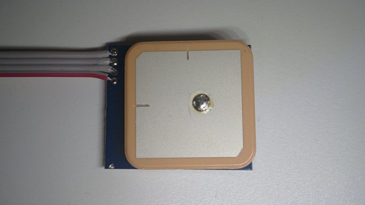
So the unit I received was called as a “GPS Module with Ceramic Antenna GPS Receiver TTL 9600 for Ublox Model Aircraft”. It is a small GPS board with a four pin connector, four solder-points and an integrated ceramic antenna. Zero indication about the order of pins. All I knew was the following:
- This is a 3.3V unit with the baud rate of 9600 bps
- The included cable has the colors red – black – yellow – white, but it can be reversed
- The pins on these units are VCC, GND, TX and RX and they use simple UART communication.
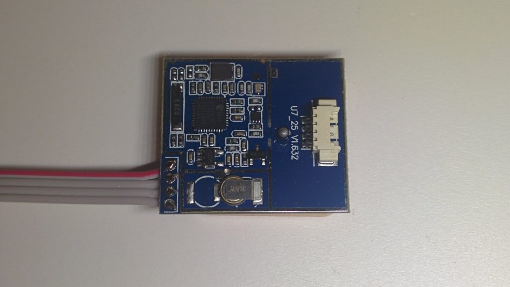
First, using a continuity tester I made sure that the four pin connector was the same as the four solder-points (it was). Then, to make things easier I soldered a ribbon cable with breadboard pins to these four points.
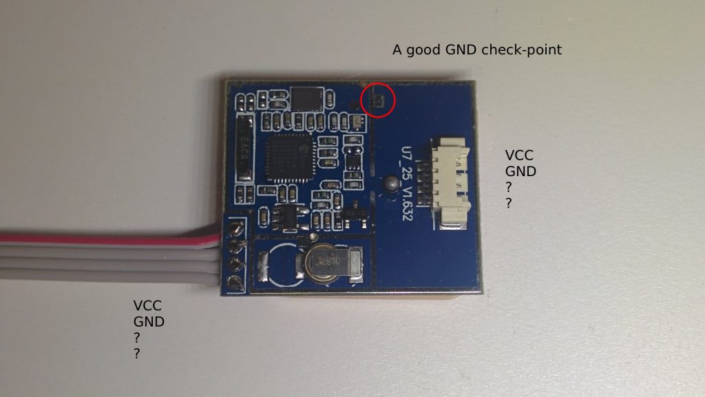
It is always a good idea to find the ground first, so I started to look for a ground plane on the unit and for an accessible pad which is connected to it. The silver colour lines on this unit are all ground. I was sure of that because I received a small metal shielding that goes around the IC-s on the unit (not on the image), and that should be soldered to these lines. So I found the GND on the board and using the continuity tester I also found the corresponding pin. Knowing the colours of the provided cable I also identified the VCC (3.3V) pin.
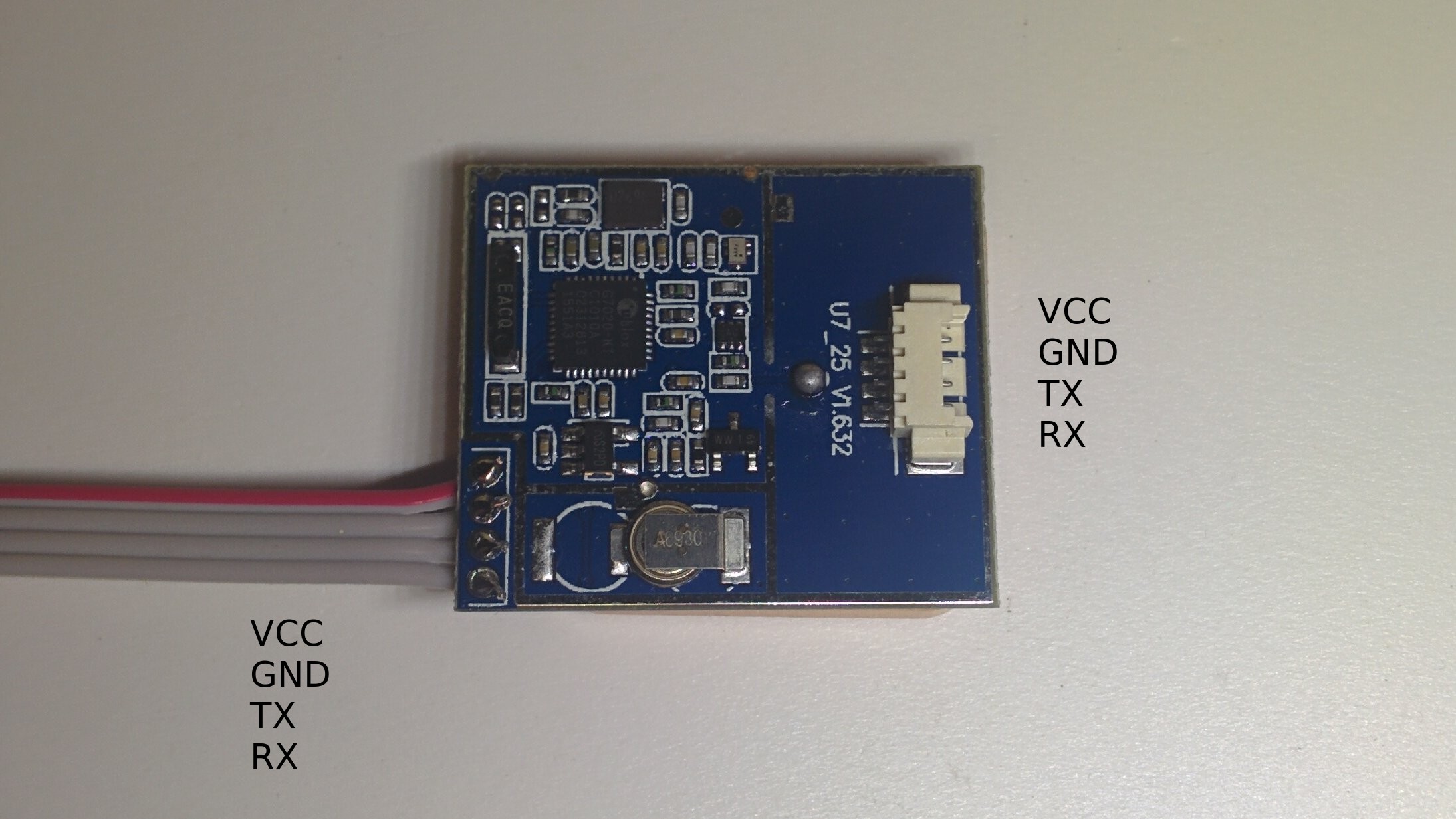
All that was left was to find out which is TX and which is RX. Since these units start to spit out messages as soon as they are powered, this was not too hard either. I powered up the unit now that I knew the GND and VCC pins and probed the two remaining pins with my oscilloscope.

I used a trigger level of somewhat over 1 volt and set the scope in single acquision mode. While holding the probe to one of the points I saw a nice picture of transmission. Using the decode function I could even double-check if this was really what I wanted:

Hooray, we can see the beginning of a GPRMC message. Instead of an oscilloscope a bright LED with a current limiting resistor could also work. You connect the cathode to GND and the anode to the tested pin through a resistor. If the LED is blicking you found the TX line. The last pin is RX, the pinout is now completely known.
Well, thats it. We have the pinout, now we can use the unit in whatever configuration we want.
thanks for the pin out!!!
Have the Banggood version no cable but will use your method (w/LED) Thank you for post.