
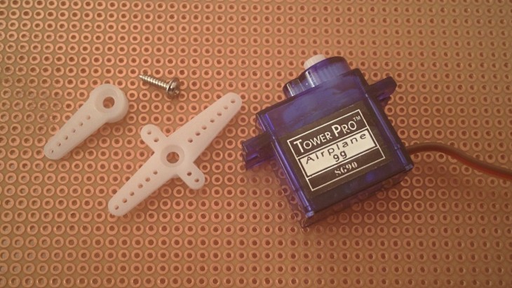
RC servo motors are probably the most popular actuators controlled by Arduinos. They come in many different sizes and shapes but for keeping it simple I’m going to write about a small, analog servo which is quite popular among DIY enthusiasts. Let’s disassemble it and see what’s inside!
Disassembly
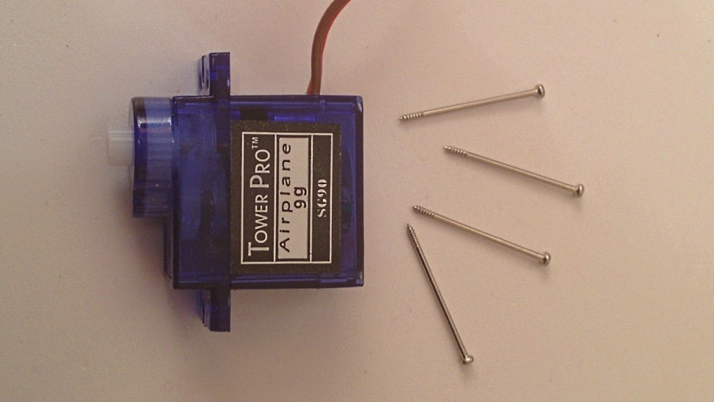
First, we remove the four tiny screws which hold the device together:
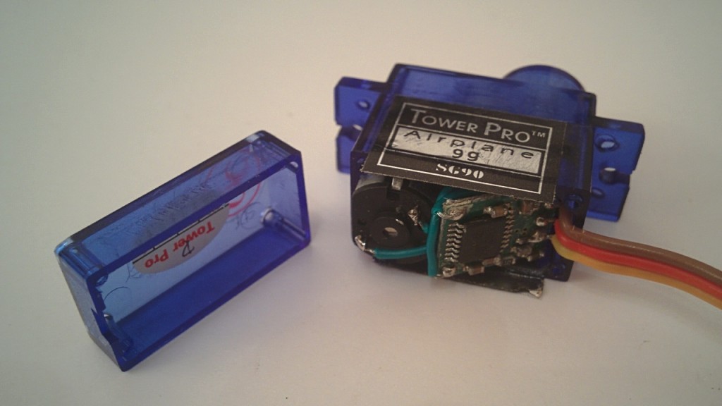
Now, this servo can be opened at two locations. If we open the bottom part we can take a look at the analog electronics and the back of the DC motor.
If we remove the top part we can see the shaft of the DC motor with a small metal gear, the integrated plastic gearing and below that, on the left: the top of the potentiometer.
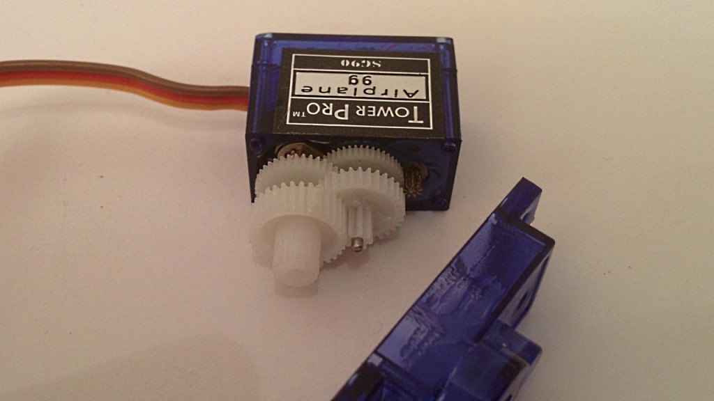
So we found basically everything that’s necessary for a servo to function. How does it actually work?
- The servo gets an electrical signal through the wires (more on that later). This signal is the reference value, it tells the servo the desired position.
- By measuring the resistance of the potentiometer it knows the current position of the shaft.
- It calculates the difference of the actual and the desired position. This is called the error value.
- Using its closed loop control, it rotates the DC motor based on the error value.
- The torque is increased, velocity is decreased by the gearing.
- When the shaft reaches the desired position, the error is zero and the DC motor stops.
Pinout and electrical properties
An analog RC servo is driven with 3 wires:
- ground (black or brown)
- power (red)
- signal (yellow or orange)
Most of the servos run on 5 to 6 volts DC but be very careful, only the tiniest ones can be powered directly from an Arduino. Anything that draws more than a few hundred milliamps should get a separate power supply.
The servo expects a PWM (pulse width modulation) signal on its yellow or orange wire. Examine the following diagram:
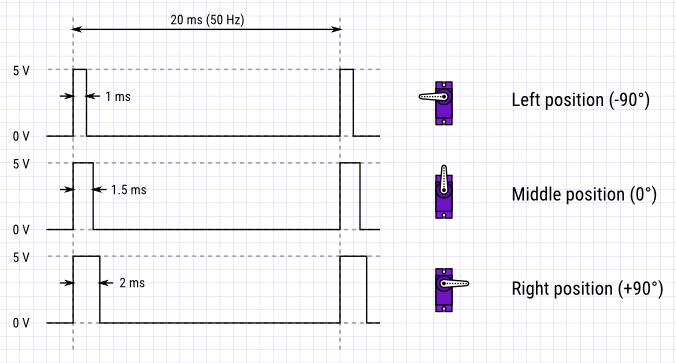
As you can see the servo needs a short pulse every 20 milliseconds and moves its arm according to the length of this pulse. The values on the diagram are the most common but some servos expect the pulses to be between 0.5 and 2.5 milliseconds and some only move 90°.
How do we produce a series of well controlled voltage pulses?
Stay tuned for the next parts…