
Earlier this year I started a small project to create a whistle controlled IKEA lamp. In the first prototype I used an Arduino nano and a simple microphone amplifier built from discrete parts. In this post I’m going to present this circuit.
Building the circuit
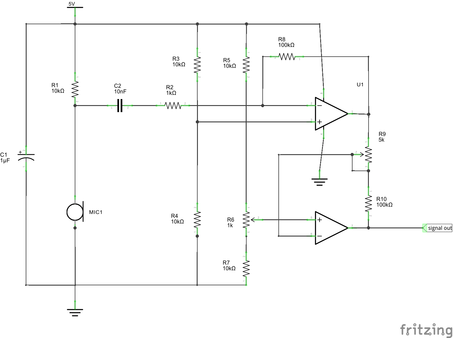
The heart of the circuit is the LM358N IC, which is a low power, general purpose dual operational amplifier. The two stages are connected in series and in inverting configuration. The amplification can be adjusted between around 2000 and 10000 with potentiometer R9 and the zero offset is set with with potentiometer R6.
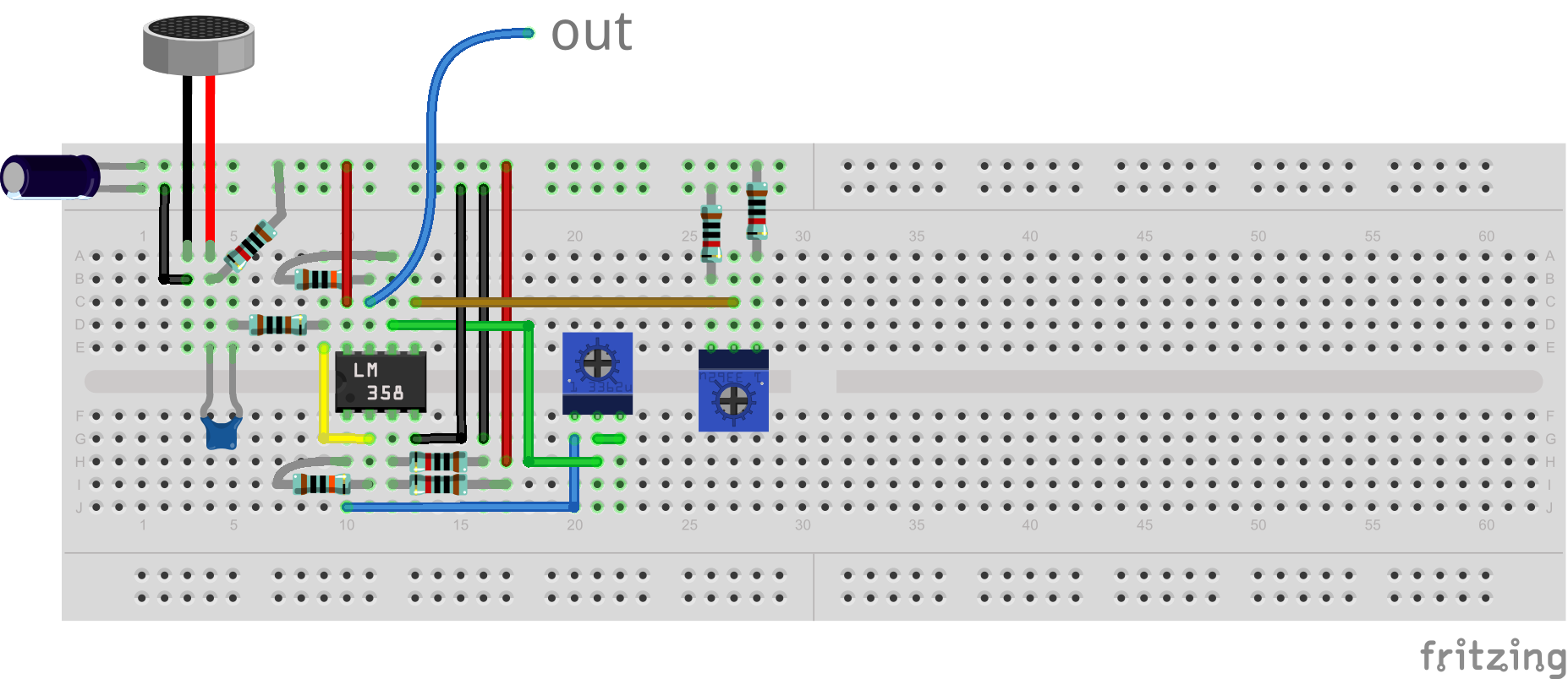
The circuit nicely built on a breadboard should look like this:
And in reality it looks like this:
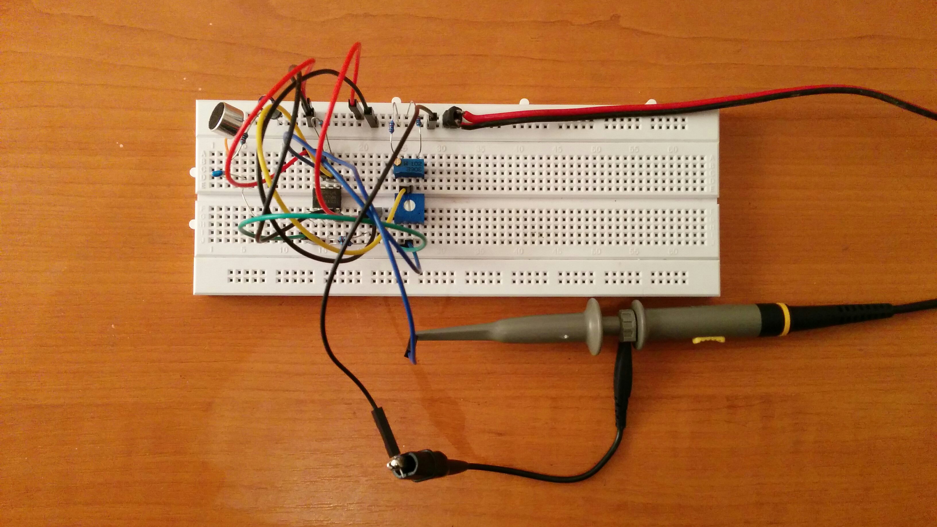
Notice I’m using a multi-turn precision potentiometer for offset setting. This is essential for correctly tuning our amplifier in the next step.
Fine-tuning the circuit
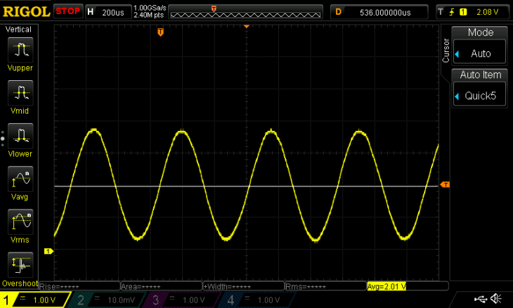
Now, the bad news is that you need an oscilloscope to fine-tune the circuit. The good news is that the process is quite simple. First, lets adjust the offset to middle position and the amplification to the lowest possible. Connect the probe to the output of the amplifier and power up the circuit. We immediately see some noise on the display. Start increasing the amplification while making some noise until you see that the waveform is clipped. Here’s a waveform of me whistling:

As you can see, the upper part of the “sine” is missing. Theoretically if R3, R4, R5 and R7 are perfectly equal, the offset would be exactly the half of the supply voltage and there would be no need for compensation. But since there’s a slight spread in the real resistance values, the offset is not in the middle and the output reaches the maximum of what the op-amp can produce. We included R6 to avoid this and we must set it correctly to compensate the differences. I do this by setting the oscilloscope to single-run mode and clap once. This produces a waveform like this:

A single clap easily makes a waveform that is clipped at both ends, so we can measure the limits and adjust the offset correctly. Here, I added two cursors: the maximum voltage is 3.82 V, the minimum is 0.02 V. From these, the optimal middle position would be (3.82 + 0.02) = 1.92 V. So lets resume the display of the oscilloscope and start turning the potentiometer until we reach an average voltage of ~1.92 volts. A loud whistle now looks like this:

Lets reduce the amplification a little bit:

Now we have a 0-4 V nice analog signal that is perfect for an Arduino board.
What’s even better? You can save the hassle by using an off-the-shelf microphone module for Arduino. I just bought one from e-bay and waiting for it. I’m curious what is a $1 module capable of.
